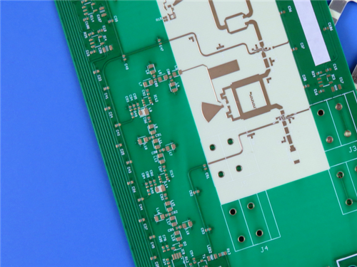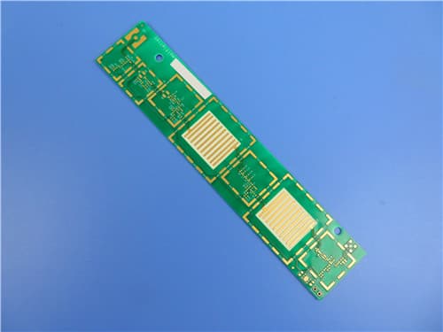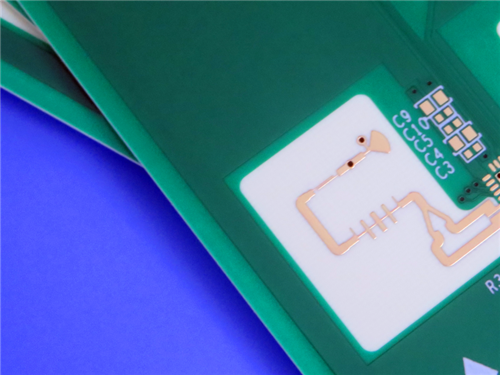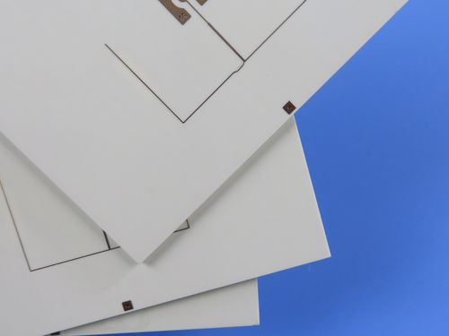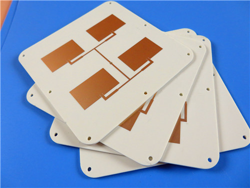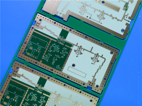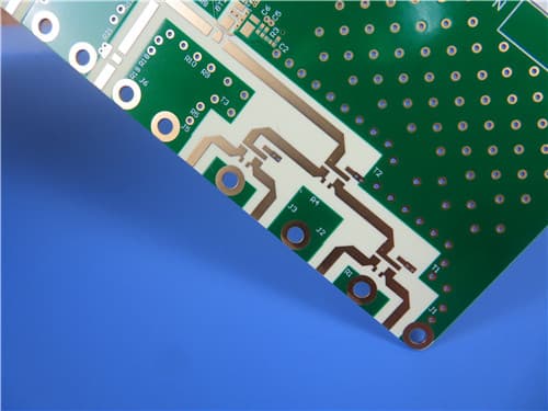
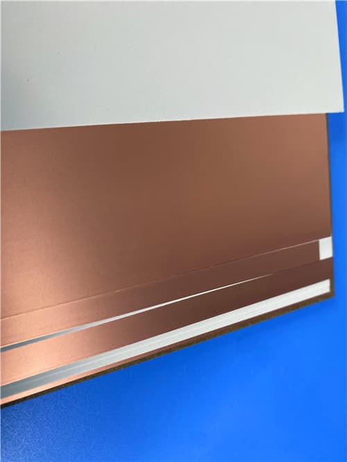
12-Layer Hybrid PCB – RO4350B + RO3010 ENEPIG High Frequency Multilayer1. Introduction to Hybrid RO4350B+RO3010 PCB This 12-layer hybrid rigid PCB combines Rogers RO4350B hydrocarbon ceramic laminate and RO3010 ceramic-filled PTFE composite, bonded with RO4450F prepreg. The design features top and bottom 4mil RO4350B layers with middle RO3010 cores of 5mil, 10mil, and 25mil thicknesses, offering a unique mixed-dielectric solution for high-frequency and microwave applications requiring different dielectric constants within a single board. RO4350B provides Dk 3.48±0.05 and low loss (Df 0.0037@10GHz) with standard FR-4 processing, while RO3010 offers Dk 10.2±0.3 for high dielectric constant requirements. This hybrid construction enables optimized impedance control and signal integrity in complex RF designs.
2. Key Features
3. Benefits
4. PCB Construction Details
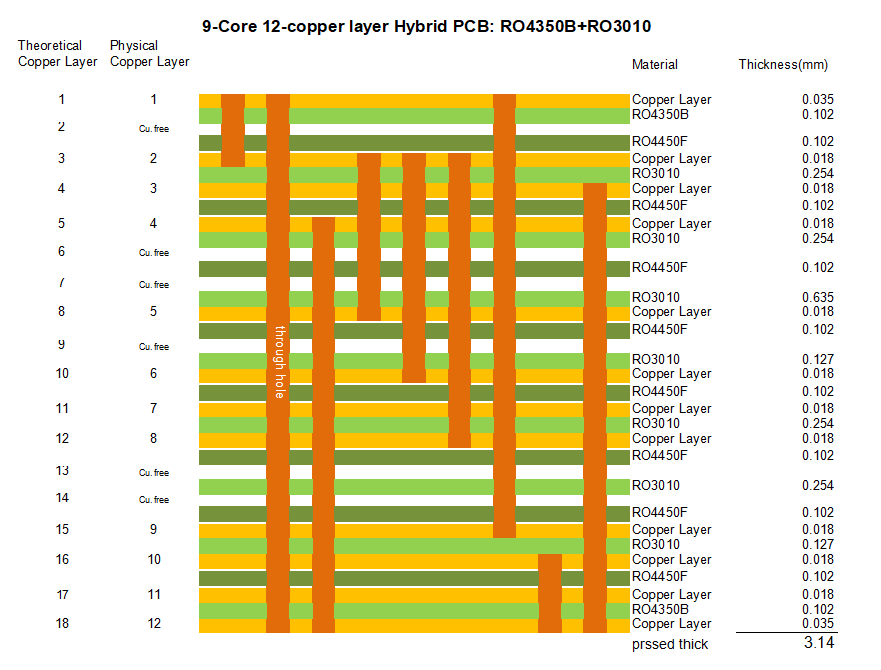
5. PCB Stackup (12-Layer Hybrid Structure) Layer 1 (Top Copper) – 35 μm (1 oz) RO4350B – 0.102 mm (4mil) Layer 2 (Cu. free) – RO4450F – 0.102 mm Layer 3 (Copper) – 18 μm (0.5 oz) RO3010 – 0.254 mm (10mil) Layer 4 (Copper) – 18 μm (0.5 oz) RO4450F – 0.102 mm Layer 5 (Copper) – 18 μm (0.5 oz) RO3010 – 0.254 mm (10mil) Layer 6 (Cu. free) – RO4450F – 0.102 mm Layer 7 (Copper) – 18 μm (0.5 oz) RO3010 – 0.635 mm (25mil) Layer 8 (Copper) – 18 μm (0.5 oz) RO4450F – 0.102 mm Layer 9 (Cu. free) – RO3010 – 0.127 mm (5mil) Layer 10 (Copper) – 18 μm (0.5 oz) RO4450F – 0.102 mm Layer 11 (Copper) – 18 μm (0.5 oz) RO3010 – 0.254 mm (10mil) Layer 12 (Copper) – 18 μm (0.5 oz) RO4450F – 0.102 mm Layer 13 (Cu. free) – RO3010 – 0.254 mm (10mil) Layer 14 (Cu. free) – RO4450F – 0.102 mm Layer 15 (Copper) – 18 μm (0.5 oz) RO3010 – 0.127 mm (5mil) Layer 16 (Copper) – 18 μm (0.5 oz) RO4450F – 0.102 mm Layer 17 (Copper) – 18 μm (0.5 oz) RO4350B – 0.102 mm (4mil) Layer 18 (Bottom Copper) – 35 μm (1 oz) Total pressed thickness: 3.14mm
6. PCB Statistics Components: 38 Total Pads: 124 Thru Hole Pads: 52 Top SMT Pads: 72 Bottom SMT Pads: 0 Vias: 96 (including blind vias) Nets: 3 7. Blind Via Structures
8. RO4350B High Frequency Circuit Materials RO4000® hydrocarbon ceramic laminates are designed to offer superior high frequency performance and low cost circuit fabrication. The result is a low loss material which can be fabricated using standard epoxy/glass (FR-4) processes offered at competitive prices. RO4350B laminates feature Dk 3.48±0.05, Df 0.0037@10GHz, Tg >280°C, and CTE matched to copper (10/12/32 ppm/°C). The material's thermal coefficient of expansion provides excellent dimensional stability and reliable plated through-hole quality.
9. RO3010 High Frequency Circuit Materials RO3000® series high frequency circuit materials are ceramic-filled PTFE composites intended for use in commercial microwave and RF applications. RO3010 laminates offer a high dielectric constant of 10.2±0.3 at 10GHz, with low dissipation factor of 0.0023. RO3010 materials exhibit CTE matched to copper (16/16/24 ppm/°C) and provide excellent dimensional stability and reliable plated through-hole performance, making them ideal for antenna and high-frequency component applications. 10. Material Properties Summary
11. Primary Application Areas
12. Quality Assurance
|
Get a Quick Quote
Fill in the form below and our engineers will reply within 24 hours with technical specifications and pricing for 12-Layer Hybrid RO4350B+RO3010 ENEPIG PCB.